Every watt that does not reach your device becomes heat inside the case, and thermal design decides whether that heat stays harmless or turns into derating, returns and early failures. For OEM teams, understanding conduction, convection and the materials in between is how you judge whether a compact charger will hold its rated output in the real world — not just on the label.
Why heat is the real limit in charger design
Heat is the real limit because a 65W charger must shed roughly 5W of loss from a volume smaller than a matchbox. Efficiency sets how much heat exists; thermal design decides whether it reaches the case, how hot the surface gets and how long components last. Two chargers with the same chip can run 10–15°C apart on the skin because their thermal paths are different.
That gap is exactly why "same wattage, same GaN device" does not mean "same product." The thermal design is where a charger's real sustained performance is decided.
Conduction paths inside a compact brick
Heat inside a charger travels by conduction first: from the semiconductor die to its pad, into the PCB copper, through potting or thermal materials, into a shield or the case, and finally to the surrounding air. Every gap in that chain acts as an insulator, which is why copper area, potting coverage and shield design matter more than most buyers assume.
- PCB copper: larger planes and dedicated heat-spreading areas carry heat sideways, away from hot spots.
- Potting compound: fills air gaps so heat conducts to the case instead of pooling inside the enclosure.
- Aluminum shields: double as EMI shields and heat paths, moving heat toward cooler case surfaces.
Texas Instruments' power supply design seminar library covers the converter-side thermal design in detail; the material science behind these paths is explored in heat-sink research on electronics cooling.
Convection, enclosures and skin temperature limits
Once heat reaches the case, natural convection carries it away — and a passive brick has no fan to help. Enclosure design shapes how effectively that happens: vent placement, wall thickness, surface area and the way the board is mounted all change skin temperature.
Skin temperature is also a compliance issue. Chargers must respect touch-temperature limits in IEC/UL safety standards, so the enclosure cannot simply get as hot as the components allow. The design must shed enough heat to keep accessible surfaces inside the limit while internal hotspots stay within component ratings.
When designs add potting, thermal pads or fans
As wattage climbs, passive conduction and convection stop being enough, and factories add engineered thermal elements. Understanding which one a design uses — and why — tells you a lot about its quality.
- Thermal potting: the standard upgrade for compact bricks; fills voids and bonds heat to the case.
- Thermal pads and interface materials: fill the gap between components and shields; newer materials use advanced fillers to raise thermal conductivity.
- Phase-change materials (PCM): absorb heat during spikes and release it during idle, useful for intermittent high-load products.
- Fans: rare in travel chargers, but used in high-power desktop adapters where acoustic noise is acceptable.
How thermal design shows up in performance claims
Thermal design is visible in performance claims if you know where to look: sustained output versus peak, derating behavior and skin temperature. A charger that holds 65W for two minutes then drops to 45W has a thermal problem, no matter what the label says.
When comparing suppliers, compare the same test: 30 minutes of full load at a defined ambient, measuring skin temperature and output stability. That single test exposes more design quality than any spec-sheet comparison.
Thermal questions to include in an RFQ
Put thermal requirements in the RFQ so every supplier answers the same way. These five questions are the minimum for any compact charger program.
- What is sustained output after a 30-minute full-load soak at 25°C and 40°C ambient?
- What skin temperature does the enclosure reach at full load in that test?
- Can you provide the derating curve — output power versus time and ambient temperature?
- What are the temperatures on the GaN device, transformer and bulk capacitor during the soak?
- Can you share thermal camera images or test videos as evidence?
Derating curves: how chargers protect themselves at high temperature
Thermal derating is the charger's safety valve: as internal temperature climbs, output power is reduced to protect components. The table below is illustrative, not a spec for any specific model — the pattern is what matters.
| Ambient temperature | Well-designed 65W charger | Weak thermal design |
|---|---|---|
| 25°C typical indoor | Sustains 65W for hours | Sustains 65W briefly, then starts derating |
| 35°C warm room / summer | Sustains 65W | Drops toward 50–55W |
| 40°C hot environment | Holds full or near-full output | Drops toward 45W |
Temperature-accelerated aging models show why this matters: capacitor and component life roughly doubles for every 10°C drop in operating temperature, so derating behavior is also a lifespan story, not just a performance one.
Skin temperature limits in IEC/UL safety standards
IEC/UL safety standards define how hot accessible surfaces may get, with limits that depend on material and touch duration — the IEC 62368-1 touch-temperature framework is the reference most charger designs target. Metal surfaces generally must stay cooler than plastic ones, and limits are stricter for surfaces touched repeatedly.
The engineering consequence: a charger's thermal design must meet the skin limit while keeping internal hotspots inside component ratings. Designs that barely pass certification at 25°C often fail at 40°C ambient, which is why the RFQ should demand data at both conditions.
How to measure enclosure temperature on real samples
Measurement method matters as much as the number. On a real sample, use thermocouples at defined points plus a thermal camera to find hotspots, under controlled ambient with the charger at full load for at least 30 minutes.
- Record ambient temperature and airflow conditions; both change results dramatically.
- Measure the hottest accessible surface point, not an average.
- Log output power during the soak to catch derating as it happens.
- Repeat at 25°C and 40°C ambient before accepting any performance claim.
Field failure modes linked to weak thermal design
Weak thermal design shows up in the field as a predictable set of failures, and warranty data is where they surface. Electrolytic capacitor aging, solder joint fatigue and connector wear all accelerate with heat; users also report output drops, hot cases and, in extreme cases, discolored housings or smell.
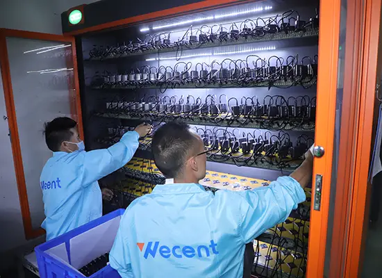
These are the exact failure modes that load-aging and thermal testing catch before shipping. That is why our factory runs 100% functional testing and load aging at multiple quality-control gates, with per-batch inspection reports available to buyers.
How thermal engineering shifts BOM and tooling cost
Thermal engineering is not free: potting compounds, aluminum shields, thicker copper, vented tooling and additional test time all add cost. The trade-off is usually worth it — a cooler charger means fewer returns and lower warranty cost — but the price appears in the BOM and tooling line items.
When comparing quotes, ask what thermal elements are included at the quoted price. A "too cheap" quote often means the thermal strategy was removed, and the savings will reappear as derating complaints and warranty claims.
FAQ
How do chargers dissipate heat?
Mostly by conduction from components to the case, then natural convection to the air; compact bricks have no fans. Potting, copper planes and aluminum shields improve the conduction path, while vents and surface area help convection.
Is it normal for a charger to get hot?
Yes — small 65W chargers reach 60–70°C under full load in normal conditions. Concern starts when output drops, plastic smells, or skin temperature stays above 75°C in a normal room.
What is thermal derating in a charger?
Derating means the charger reduces output power as temperature rises, protecting components from damage. A well-designed unit sustains full wattage at 35–40°C ambient; a weak design drops output quickly in summer conditions.
What thermal tests should I ask for?
Ask for full-load soak tests at 25°C and 40°C ambient, skin temperature reports and derating curves. Compare sustained wattage over 30 minutes rather than peak output on the label.
Evaluating a charger design or comparing suppliers on thermal behavior? Send your wattage targets, form factor and ambient requirements to our team through the contact page, and ask for the thermal test evidence on the models you are considering — we build chargers as our core business, so heat is a design input, not a hidden spec.
This article is part of GaN Chargers, the guide that covers this topic in decision order.