
The same 65W of output can arrive in a brick twice the size of a competitor's — and the difference is power density, not just marketing. For OEM buyers, density targets decide which components, thermal strategy and tooling costs your product will carry, so it pays to understand where the savings come from and which claims are worth trusting.
What power density actually means for a charger
Power density for a charger means rated output watts divided by external volume, usually stated in W/cm³ or W/in³. A 65W GaN charger at 1.0 W/cm³ is roughly half the volume of a comparable silicon design, because higher switching frequency shrinks the transformer and lets the whole power stage fit in a smaller enclosure. Always compare density using the same measurement method — volume including or excluding prongs changes the number by 20–30%.
Where the size savings come from: switching frequency and magnetics
The transformer and magnetic components dominate charger volume, and their size scales inversely with switching frequency. Silicon chargers typically switch at tens to a few hundred kilohertz; GaN devices switch in the megahertz range, which allows a much smaller transformer core and fewer winding turns for the same power transfer.
- Higher frequency → smaller magnetics: the core cross-section needed falls as frequency rises, shrinking the heaviest component in the case.
- Fewer and smaller passive parts: input filters and output capacitors shrink when the converter runs faster.
- Integration: modern GaN power ICs put the switch and driver in one package, cutting board area and parasitic inductance that would otherwise force larger components.
This is the mechanism behind the common question "why are GaN chargers smaller" — the answer is magnetics, not magic. EPC's GaN education resources and the IEEE Power Electronics Society's coverage of fourth-generation GaN document how frequency and integration keep advancing.
Thermal consequences of shrinking the enclosure
Shrinking the case concentrates the same heat into less surface area, so a smaller charger runs hotter at the same efficiency. A 65W GaN charger dissipating roughly 5W of loss in a palm-size case already needs deliberate thermal design; halving the volume makes the thermal path the binding constraint.
The practical consequence is that power density and thermal performance are traded against each other. A design can be very dense on paper, but if it derates after ten minutes at full load in a warm room, the density number misrepresents the real product. This is why density claims should always be paired with sustained-output and skin-temperature data.
Realistic power density at 20W, 65W, 100W and 140W
Realistic density depends on the wattage tier because form factor, plug requirements and thermal budget differ. The ranges below are illustrative for current GaN designs — always verify with the supplier's measured volume and sustained-output data.
| Charger tier | Typical external volume | Indicative density | Notes |
|---|---|---|---|
| 20W phone charger | 25–45 cm³ | 0.45–0.8 W/cm³ | Small, but plug and housing dominate volume |
| 65W travel charger | 45–75 cm³ | 0.85–1.2 W/cm³ | Density sweet spot for foldable plugs |
| 100W travel/laptop | 70–110 cm³ | 0.9–1.3 W/cm³ | Thermal management becomes critical |
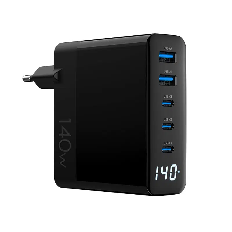
| 140W desktop/travel | 90–150 cm³ | 0.9–1.5 W/cm³ | Multi-stage designs; sustained output varies |
The numbers illustrate a pattern, not a spec: power density claims are only comparable when the measurement method and test conditions are identical. Ask suppliers for volume including and excluding the prongs, and for the wattage that can be sustained, not just the label rating.
How to compare power density claims between suppliers
Comparing density claims requires normalizing three variables: volume measurement, output definition and thermal condition. Two suppliers quoting the same W/cm³ can be describing different products if one measures the bare enclosure and the other includes the plug body.
- Use the same formula: rated output watts ÷ external volume.
- Decide whether prongs count; state it in your RFQ so all suppliers answer the same way.
- Compare sustained output at 25°C and 40°C ambient, not peak label wattage.
- Ask for a photo with a ruler or a 3D model volume to verify the claimed dimensions.
What to ask an OEM before locking a compact design
Before you approve a compact form factor, the supplier should prove the density is real under your usage conditions. These questions separate a well-engineered small charger from a squeezed one.
- What is the sustained output after a 30-minute full-load soak at 40°C ambient?
- What skin temperature does the enclosure reach at full load in that test?
- What is the derating curve, and at what ambient does output start dropping?
- What EMI margin did the design show in certification testing?
- Which components were derated to fit the smaller case, and what does that do to lifespan?
Power density benchmarks you can compare
For benchmarking, focus on watt-per-cubic-inch figures from comparable categories rather than absolute numbers, because plug standards change the envelope. A foldable-plug 65W EU travel charger will always be less dense than a US-only fixed-prong design, yet the travel version may be the better product for your market.
- Compare within the same plug region and form-factor class.
- Benchmark against current models from reputable brands, not press-release claims.
- Track density together with weight, because hollow shells can inflate volume without adding real capability.
Where ultra-compact designs cut corners
Extreme density targets invite compromises that are invisible on a spec sheet. Understanding where corners get cut helps you decide which trade-offs are acceptable for your brand.
- Thinner thermal management: less potting or smaller heat spreaders mean higher operating temperatures and faster capacitor aging.
- Reduced bulk capacitance: smaller input caps save space but increase ripple and can affect hold-up time under brownouts.
- Tighter electrical margins: reduced creepage and clearance can erode safety margins if not carefully managed.
- Weaker mechanical structure: thinner housings and lighter connector mounting can fail drop tests or repeated plug cycles.
Thermal and safety limits of small enclosures
Small enclosures face both performance and regulatory limits. Skin temperature is capped by touch-temperature limits in IEC/UL product safety standards, and the design must also survive the internal temperatures that those skin limits imply.
The safe zone for a passive brick is bounded: below roughly 75°C skin temperature under normal conditions, with internal hotspots kept within component ratings. A design that sits near these limits continuously will derate sooner and age faster, which is why "small and cool" is a better engineering goal than "small at any cost".
How density targets affect OEM cost
Higher density generally means a more expensive BOM: better GaN devices, custom transformers, thermal materials, higher-grade capacitors and more complex tooling. The cost curve is not linear — pushing a 65W design from 0.9 to 1.2 W/cm³ can cost noticeably more per unit than going from 0.7 to 0.9.
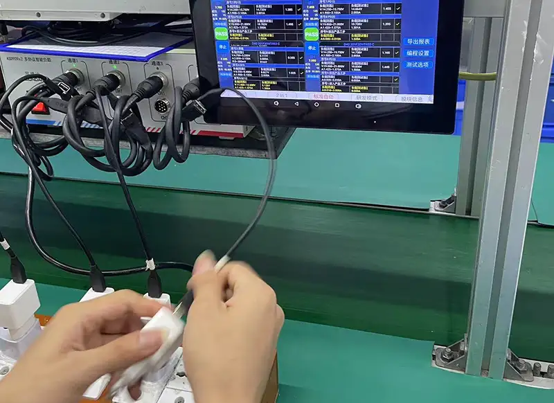
For a factory, density targets also affect OEM/ODM program structure: quick OEM launches reuse proven high-density platforms, while full ODM projects carry the engineering cost of a custom enclosure and thermal validation. Our factory runs the thermal and load-aging tests that density claims depend on, and quality control verifies them per batch.
A quick checklist for comparing compact chargers
Use this checklist when evaluating any compact GaN charger, whether you are comparing suppliers or reviewing your own design targets.
- [ ] Power density calculated with a stated measurement method
- [ ] Sustained output verified at 25°C and 40°C ambient
- [ ] Skin temperature measured at full load
- [ ] Derating curve provided
- [ ] EMI and safety margins documented
- [ ] Key components identified and derating policy explained
- [ ] Warranty and after-sales terms confirmed
FAQ
Why are GaN chargers smaller than silicon chargers?
GaN switches at much higher frequencies, which shrinks the transformer and magnetic components that dominate charger volume. Higher frequency plus integrated GaN power ICs let the entire power stage fit in a smaller enclosure at the same wattage.
What is a good power density for a 65W GaN charger?
Current designs typically land between 0.85 and 1.2 W/cm³ measured on the external enclosure, depending on plug type and thermal strategy. Always compare using the same measurement method and check sustained output, not just the density number.
Does higher power density mean worse thermals?
Not automatically, but the risk is real. Denser designs concentrate the same heat into less surface area, so the thermal design — potting, copper area and housing — decides whether the charger stays cool or derates quickly.
How do I measure charger power density myself?
Divide rated output watts by external volume (W/cm³ or W/in³). Measure external dimensions of the enclosure, decide whether prongs count, and state the method so comparisons are apples-to-apples.
Choosing a compact charger design or comparing supplier density claims? Send your wattage targets, plug regions and volume constraints to our team through the contact page — we will share sustained-output and thermal data for the models that fit your plan, so density claims stay honest.
This article is part of GaN Chargers, the guide that covers this topic in decision order.