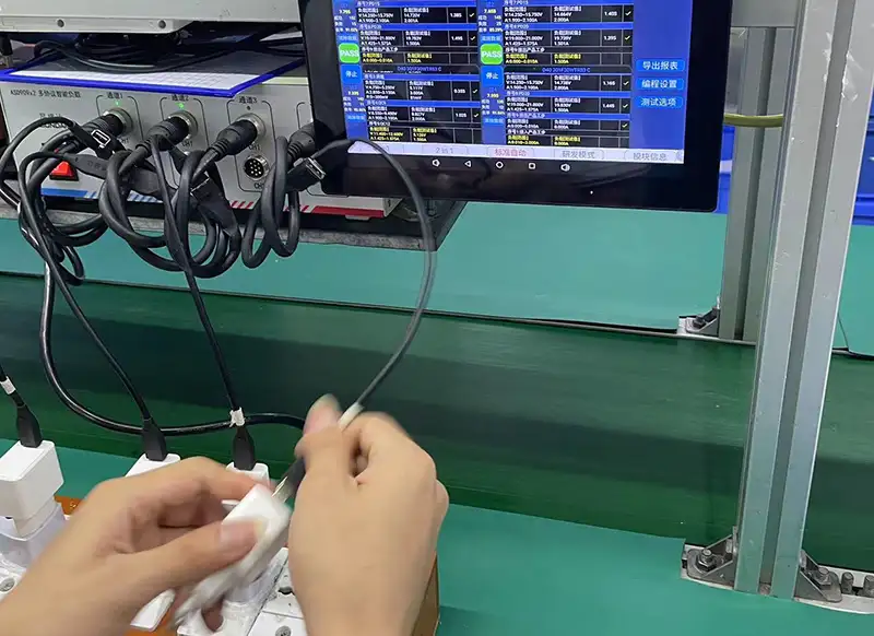
"Runs cool at 45°C" is a claim with a lot of hidden assumptions: where it was measured, at what load, for how long, in what ambient. For buyers, a temperature claim is only as good as the test behind it — this guide explains the measurement methods, conditions and documentation you should demand.
Why temperature testing matters for safety and claims
Temperature testing protects both users and your brand. Skin temperature is regulated by safety standards, and every 10°C of operating temperature roughly doubles the aging rate of capacitors and solder joints — a pattern documented in CALCE reliability research — so thermal behavior also predicts lifespan and warranty cost. A "45°C claim" without a defined test is marketing, not data.
The purpose of a temperature test is to answer three questions: how hot does the surface get, how hot do internal components get, and does the charger hold rated output while staying inside limits?
There is also a commercial dimension: temperature is the spec customers feel. A charger that gets uncomfortably hot generates reviews and returns even when it is technically within limits, while a cool-running design earns trust and repeat sales. For a brand, defining a thermal test is also defining a product promise — and a 45°C claim without the test behind it is the fastest way to make that promise unverifiable.
Thermocouple and thermal camera methods
Two measurement methods are used together in serious testing.
- Thermocouples: glued or taped at defined points (case hotspot, GaN device, transformer, bulk capacitor) and logged over time. They give exact, continuous temperatures.
- Thermal cameras: show the whole surface at once and reveal hotspots that spot measurements miss, but require careful emissivity settings and calibrated reference points.
Neither method alone is enough: thermocouples confirm exact numbers, cameras confirm you measured the right spot.
Good practice starts with a thermal camera survey to find the hotspot, then places thermocouples there and on the key components (GaN device, transformer, bulk capacitor, output rectifier). Thermocouple attachment matters: thermally conductive adhesive or tape, positioned so the junction contacts the surface directly, with the lead routed away from the hotspot so it does not conduct heat. On the camera side, set the emissivity for the surface material — matte plastic and bare metal read differently — and include a reference thermocouple in the image frame for calibration. Both methods together turn a pretty picture into measured data.
Test conditions: load, ambient and enclosure
A temperature number means nothing without its conditions. The standard recipe for a meaningful charger thermal test:
- Load: full rated output, sustained for at least 30 minutes.
- Ambient: 25°C for normal claims and 35–40°C for "hot environment" claims like 45°C.
- Enclosure: the production housing, not an open board; cable and plug position matter.
- Airflow: natural convection in still air unless the claim says otherwise.
Two conditions are most often skipped. First, soak time: 30 minutes is a minimum, and the real requirement is that temperatures reach a plateau — if the reading is still climbing at 30 minutes, the test is not finished. Second, input voltage: most tests run at 230V because that is efficient, but a charger's worst thermal case is often at 100–120V, where input current is higher. A claim made at one voltage does not automatically hold at another, so state the input condition on every report.
Where temperature limits come from in standards
Touch-temperature limits come from product safety standards such as IEC 62368-1, which set different thresholds for metal and plastic surfaces based on touch duration. Internal component temperatures must also stay within each part's rating, which is usually the tighter constraint.
In practice, accessible-surface limits typically fall between roughly 55°C and 75°C depending on material and contact duration, while internal components have their own absolute maximums from datasheets (capacitors, semiconductors and the transformer core each have different ratings). The binding limit is whichever is reached first — often the internal component rather than the surface. That is why a report that only measures the case tells you less than one that measures both.
How to compare supplier thermal reports
When comparing suppliers, normalize the test conditions before comparing numbers.
| Report item | What to check |
|---|---|
| Load | Full rated output, sustained |
| Ambient | Same temperature for all claims |
| Duration | At least 30 minutes of soak |
| Measurement | Thermocouple positions + thermal camera |
| Pass criteria | Skin limit and component limits stated |
The comparison trap is accepting different protocols. One supplier may test at 25°C for 30 minutes while another tests at 40°C for two hours — and the 40°C number will look worse even if the second design is better. Put the protocol in your RFQ so every supplier runs the same test, then compare the results; the differences that remain are real design differences.
Building a simple acceptance test for samples
You don't need a certification lab to screen samples. Run a 30-minute full-load soak at 25°C ambient, measure the hottest surface point with a thermocouple, and log output power. Repeat at 40°C if your market has hot summers — the difference between designs usually shows up at the higher ambient, consistent with temperature-accelerated lifetime models.
Make the acceptance test repeatable: same fixture position, same cable, same load profile, same logging interval. Record ambient at the start and end, and photograph the setup so the test can be reproduced by another team or a third-party lab. A sample test that cannot be repeated is only slightly better than no test.
Test equipment and setup basics
Minimum equipment: a variable AC source or stable mains, an electronic load, a data logger, thermocouples, and ideally a thermal camera — with measurement guidance from power supply design references. Keep the charger in still air away from walls, use the production cable, and record ambient temperature continuously.
Calibration is the hidden requirement. Thermocouples drift, data loggers have offsets, and thermal cameras need periodic calibration against a known source. Ask what calibration evidence comes with a supplier's thermal report, and check the logging interval — a single "final temperature" without a time trace cannot show whether the temperature was stable or still rising.
Defining acceptable limits for your product
Set your own limits before testing: skin temperature below the safety-standard threshold with margin, component temperatures inside datasheet ratings, and no output derating within the claim window. Write these into your RFQ so suppliers test to the same bar.
A concrete limit set for a 65W charger might look like: skin ≤ 70°C at 25°C ambient, ≤ 75°C at 40°C ambient, bulk capacitor case ≤ 85°C, transformer ≤ 100°C, and output held at 65W for the full 30 minutes. Adjust the numbers for your wattage, enclosure material and markets, but publish them before suppliers quote — limits defined after testing are always convenient.
Comparing thermal reports between suppliers
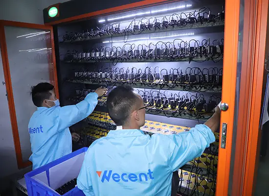
Ask every supplier for the same deliverable: a report with conditions, raw temperature log, thermal camera images and pass/fail against stated limits. Our quality-control process keeps thermal and test documentation shareable under NDA, with factory gates including load aging and per-batch inspection reports.
Interpreting thermal camera images
Thermal images are easy to fake with bad settings. Check the emissivity setting, the temperature scale and the reference measurement; a camera image without a matching thermocouple reading proves little. Treat images as supporting evidence, not standalone proof.
Building temperature testing into QA
The best suppliers build thermal checks into production QA, not just design validation — the same logic as burn-in screening in electronics manufacturing. Ask whether samples from each batch are thermal-tested, how many units, and what the pass criteria are. Temperature testing is where a "45°C claim" becomes a documented, repeatable specification instead of a slogan.
FAQ
How is charger temperature tested?
With thermocouples at defined surface and component points plus a thermal camera, at full load for at least 30 minutes at a stated ambient temperature, usually 25°C or 40°C.
What is a safe charger surface temperature?
Safety standards such as IEC 62368-1 define touch-temperature limits that depend on material and contact duration, typically between 55°C and 75°C. Above that range, or if output drops during the test, the design needs review.
Why do supplier temperature numbers differ so much?
Usually because conditions differ: load, ambient, duration, enclosure and measurement method. Normalize the test protocol before comparing any two numbers.
What should a 45°C thermal claim include?
A defined ambient, full load, soak duration, measurement points and pass criteria. Without those, the claim is not verifiable.
Setting thermal requirements for your charger program? Send your target markets and temperature limits to our team through the contact page — we will share thermal test reports and measurement methods so claims stay verifiable.
This article is part of Charger OEM & Wholesale, the guide that covers this topic in decision order.